


21 Sep Multicore Fiber: Technology, Applications, and the Future of Optical Networks
Multicore Fiber (MCF)
Executive Overview: As conventional single-core optical fibers approach their physical capacity limits, Multicore Fiber (MCF) introduces a critical new dimension for scaling network bandwidth: By housing multiple independent optical cores inside a single glass cladding, MCF multiplies spatial transmission density without expanding physical cable footprints.
- 1. What Is Multicore Fiber & How Does It Work?
- 2. Space-Division Multiplexing (SDM)
- 3. Multicore Fiber vs. Conventional Single-Core Fiber
- 4. Capacity Scaling Mechanics
- 5. Primary Application Areas
- 6. Technical & Engineering Challenges
- 7. Commercialization Status & Roadmap
- 8. Frequently Asked Questions
- Conclusion
1. What Is Multicore Fiber & How Does It Work?
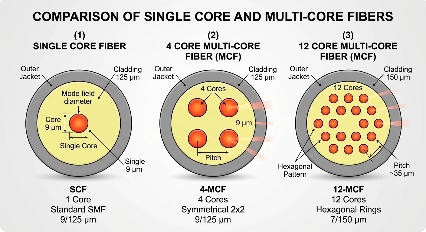
Multicore fiber (MCF) is an optical fiber containing two or more independent optical cores within a shared glass cladding.
In standard single-mode fiber (SMF), light propagates through a central core. In multicore fiber, multiple cores are arrayed within the cladding, with each core guiding a separate data stream while minimizing optical coupling between neighbors.
Physical Footprint
Recent 4-core designs maintain an outer fiber diameter comparable to standard single-core optical fiber: 125 μm.
Multidimensional Scaling
Rather than replacing existing technologies, MCF operates alongside existing multiplexing techniques. Total capacity scales with cores × wavelengths × polarizations × symbol rate.
2. Space-Division Multiplexing (SDM)
Multicore fiber is a primary driver of Space-Division Multiplexing (SDM)—the strategy of creating multiple independent physical or spatial paths within a transmission medium.
SDM can be implemented through several physical architectures:
Multicore Fibers (MCF)
Multiple distinct cores in one cladding.
Few-Mode / Multimode Fibers
Multiple spatial modes per core.
High-Density Fiber Bundles
Stacking individual fibers in larger cables.
Hybrid Approaches
Combining spatial modes and multiple cores.
3. Multicore Fiber vs. Conventional Single-Core Fiber
| Feature | Conventional Single-Core Fiber | Multicore Fiber (MCF) |
|---|---|---|
| Optical Cores per Fiber | 1 | 2 to 19+ cores |
| Spatial Channels | 1 | Multiple |
| Outer Fiber Diameter | Standard (125 μm) | Comparable footprint |
| Capacity Scaling Limits | Bound by non-linearities & OSNR | Scales linearly with core count |
| DWDM & Coherent Compatibility | Fully compatible | Fully compatible |
| Inter-Core Crosstalk | N/A | Critical design factor |
| Splicing & Alignment | Standard, mature | Requires angular/core alignment |
| Optical Amplification | Standard single-core EDFA | MC-EDFA or Fan-In/Fan-Out interfaces |
| Primary Use Cases | General telecom networks | AI Data Centers, DCI, Submarine Cables |
4. Capacity Scaling Mechanics
Single-core fibers face fundamental physical constraints known as the non-linear Shannon limit. Pushing more optical power down a single core introduces non-linear distortion, limiting signal-to-noise ratios (OSNR) and forcing higher digital signal processing (DSP) energy consumption.
Deploying more physical fibers is limited by conduit space, weight, splicing labor, and cable tray density. MCF solves this by increasing core density within the fiber itself.
Example Capacity Scaling
Assuming 800 Gb/s per wavelength and 48 wavelength channels per core:
5. Primary Application Areas
AI Data Centers
- Maximize duct capacity
- Simplify high-density patch panels and rack pathways
- Increase bandwidth density for GPU clusters
Submarine Cables
- Overcome cable weight constraints
- Increase throughput without proportionally increasing cable size
- Support high-capacity transoceanic systems
Terrestrial Backbones
- Avoid duct exhaustion
- Multiply cross-country backbone throughput
- Increase capacity within existing infrastructure
AI Data Centers & Campus Interconnects
High-density GPU clusters demand massive internal bandwidth. Facilities face tight physical constraints across rack space, conduit capacity, and cable tray loading.
Corning 4-Core Solution — March 2026
Delivers up to 4× capacity within a standard fiber footprint, relieving cable congestion in AI clusters.
SDM4 MSA Industry Initiative — March 2026
AFL, Corning, Sumitomo Electric, and TeraHop formed a Multi-Source Agreement to establish interoperability standards for 4-core passive data center connections.
Submarine Cable Systems
Transoceanic cables are bounded by physical size, weight, and installation dynamics. MCF allows subsea operators to multiply total throughput without inflating cable diameter or ship loading constraints.
Google TPU Cable
Google and NEC deployed 2-core MCF in the Taiwan-Philippines-U.S. (TPU) cable—the first commercial subsea implementation of MCF.
NTT Subsea Innovations
NTT introduced 4-core subsea fiber with custom joint boxes and terminal racks, alongside a 192-core submarine cable architecture designed to deliver 4× throughput over standard subsea builds.
410.5 Tb/s Field Demonstration
Researchers successfully transmitted 410.5 Tb/s net capacity (513.1 Tb/s gross capacity) over a 140-km deployed 7-core link in the South China Sea, featuring 0.2 dB/km attenuation and inter-core crosstalk below −60 dB/km.
6. Technical & Engineering Challenges
CROSSTALK
Optical power can bleed between adjacent cores, affecting signal quality.
AMPLIFICATION
Standard EDFAs amplify one core; multicore EDFAs are needed for integrated MCF systems.
SPLICING
Core rotation and precise angular alignment require new tools and techniques.
INTEROPERABILITY
Cross-vendor standards remain important to broader deployment.
1. Inter-Core Crosstalk
Energy leaking between adjacent cores degrades signal quality. System designers mitigate this through optimized core spacing, refractive-index trench profiling, and careful control of bending radius.
2. Optical Amplification
Fan-In / Fan-Out (FI/FO): Separates the MCF cores into individual standard single-mode fibers before entering separate EDFAs. Reliable, but adds component count and insertion loss.
Multicore EDFA (MC-EDFA): Amplifies all cores simultaneously within a single cladding using cladding-pumped erbium-doped structures.
3. Splicing & Connectorization
Splicing MCF requires rotational alignment in addition to standard X/Y position alignment, requiring high-precision visual alignment fusion splicers and multi-core ferrules.
7. Commercialization Status & Roadmap
Research & Labs
Higher core counts, including 12- to 19+ core architectures.
Field Trials
7-core links and demonstrations reaching hundreds of terabits per second.
Commercial Deployment
Google TPU Cable 2-core MCF and Corning/MSA 4-core AI data-center solutions.
Multicore fiber has transitioned from academic research to active commercialization across key network domains:
Submarine
Active deployment, including the Google TPU Cable utilizing 2-core MCF, with NTT developing 4-core and 192-core platforms.
AI & Data Centers
Rapid standardization, including 4-core solutions introduced by Corning and the SDM4 MSA vendor ecosystem.
Terrestrial Long-Haul
Pilot phases and field evaluations for high-density metropolitan and long-distance backbones.
8. Frequently Asked Questions
What is multicore fiber?
Multicore fiber is an optical fiber containing two or more distinct optical cores housed within a single glass cladding. Each core operates as an independent spatial channel.
How does MCF differ from conventional single-mode fiber?
Standard single-mode fiber contains a single optical core. MCF embeds multiple cores inside the same outer fiber profile, multiplying total capacity per cable strand.
Can multicore fiber be used alongside DWDM?
Yes. DWDM and MCF are complementary. Multiple DWDM wavelength channels can run independently through each core of a multicore fiber.
What is space-division multiplexing (SDM)?
SDM is a multiplexing methodology that creates multiple spatial channels within a single optical medium. MCF is one of the most commercially viable implementations of SDM.
What are the main benefits of multicore fiber?
Key benefits include higher bandwidth per fiber, increased physical pathway density, reduced cable tray congestion, smaller conduit requirements, and optimized infrastructure footprint for AI and subsea applications.
What are the main engineering challenges with MCF?
Core-to-core crosstalk, specialized angular fusion splicing, multi-core connector precision, and the deployment of integrated multicore optical amplifiers (MC-EDFAs).
Is multicore fiber being deployed commercially today?
Yes. Google and NEC deployed 2-core MCF in the TPU submarine cable system. Additionally, 4-core MCF solutions and industry MSAs (SDM4) are actively targeting AI data center architectures.
Conclusion
Multicore fiber adds a vital new spatial dimension to optical networking. By pairing Space-Division Multiplexing with DWDM and Coherent Optics, MCF provides the architectural headroom required to handle exponential bandwidth demand driven by AI clusters, cloud networks, and global subsea backbones.
Learn More About Advanced Optical Networking
To learn more about multicore fibers and other aspects of advanced optical networking, join our Certified Optical Network Engineer (CONE) training program.
Explore CONE Training
Jabulani Dhliwayo is Founder and Technical Director of FiberGuide, a lecturer, scientist, engineer, and optical networking expert with more than 30 years of experience in fiber optics, telecommunications, research, and product development. He develops and delivers advanced CONA and CONE training programs for telecom operators, data centers, and government organizations. His career includes senior technical and product leadership roles at Corning and Yokogawa. His expertise spans DWDM, OTN, coherent optics, ROADMs, and fiber characterization. Dr. Dhliwayo holds a Ph.D. in Physics from the University of Kent, an M.S. in Applied Physics, and a B.S. in Physics.
You can connect with him on Linkedin
Sorry, the comment form is closed at this time.