

31 May What Is Fiber Optics? How It Works, Types, Uses & Benefits
What Is Fiber Optics?
How optical fiber works, the different types of fiber, key applications, and why fiber remains the foundation of modern communications
Fiber optics is a technology that uses thin strands of glass or plastic fiber to transmit information as pulses or modulated signals of light. Unlike copper cables, which transmit data using electrical signals, optical fiber carries information using light.
Fiber optics provides extremely high bandwidth, low signal loss, long transmission distances, and immunity to electromagnetic interference. These characteristics have made optical fiber the foundation of modern telecommunications, internet infrastructure, data centers, 5G networks, and submarine communication systems.
An optical fiber consists primarily of a core, cladding, and protective coating. The core carries the light, while the cladding helps confine the light within the core.
Fiber Optics at a Glance
| Feature | Fiber Optics |
|---|---|
| Transmission medium | Glass or plastic fiber |
| Signal | Light |
| Main fiber types | Single-mode and multimode |
| Common wavelengths | 850, 1310 and 1550 nm |
| Major advantage | Very high bandwidth |
| Long-distance capability | Tens to thousands of kilometers |
| EMI immunity | Yes |
| Major applications | Internet, telecom, data centers, FTTH and sensing |
How Does Fiber Optics Work?
A fiber optic communication system converts electrical information into light, transmits that light through optical fiber, and then converts it back into electrical information at the receiving end.
The basic process is:
Electrical data → Optical transmitter → Light → Optical fiber → Photodetector → Electrical data
The transmitter typically uses a laser or LED to generate the optical signal. The light travels through the fiber and is detected by a photodetector at the receiving end.
How Does Light Stay Inside the Fiber?
Optical fiber works primarily through a phenomenon called total internal reflection.
The fiber's core has a slightly higher refractive index than its surrounding cladding. When light enters the core within the appropriate range of angles, it is reflected at the core-cladding boundary and remains confined within the fiber.
In modern communication systems, however, describing fiber simply as "bouncing light off the walls" is an oversimplification. The propagation of light is governed by electromagnetic wave behavior and the fiber's optical properties.What is the structure of optical fibers?
In its simplest form, an optical fiber consists of a core of silica typically doped with Germanium to elevate its refractive index above the surrounding pure silica cladding. Having an inner core with a refractive index higher than that of the cladding is a requirement for transmission to happen. In specialized types of optical fiber, such as pure silica core fiber, the core is composed of pure silica, while the surrounding cladding is doped with materials that reduce its refractive index relative to the core. A third layer made of plastic protects the glass fiber from breakage, prevents moisture intrusion, and adds flexibility. In certain applications, such as enterprise networks, an additional outer coating may be applied over the primary layer to enhance strength and durability.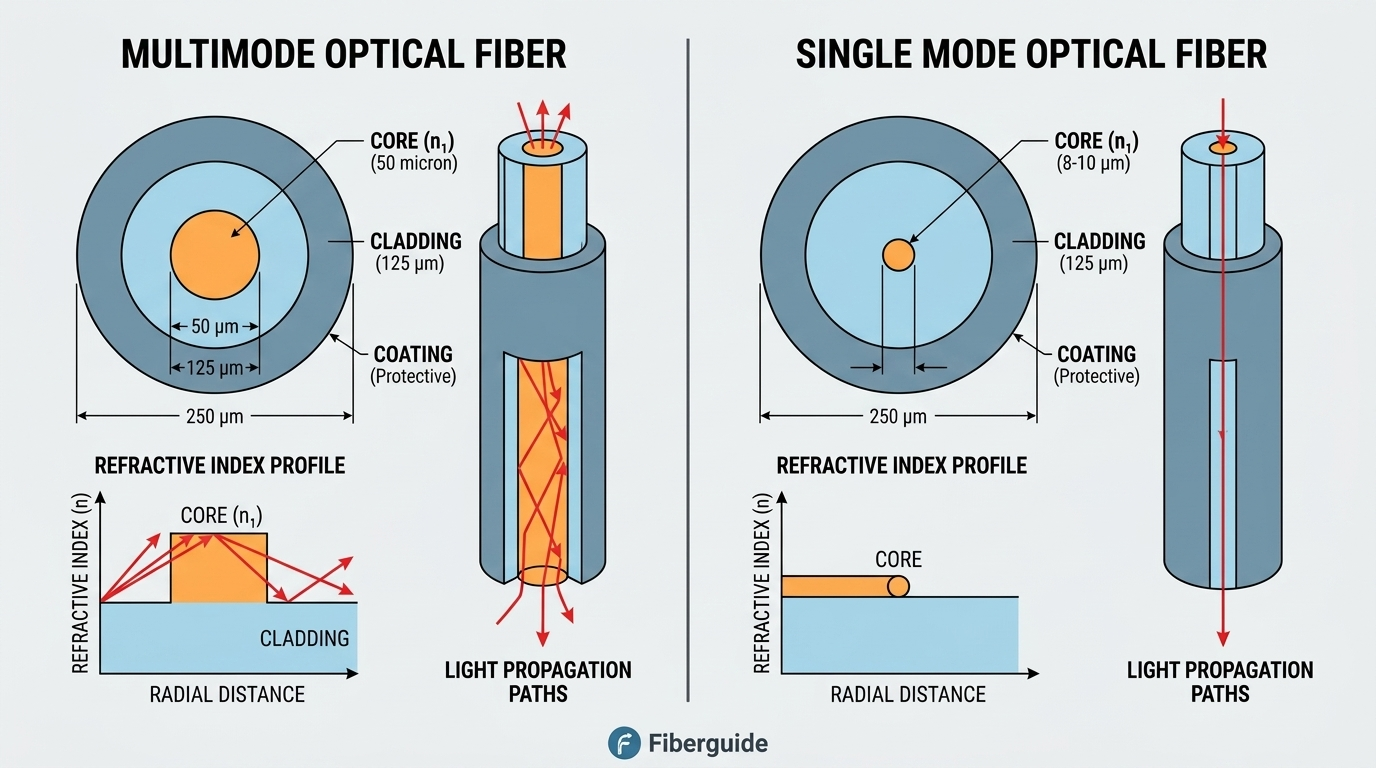
How is light transmitted through optical fiber?
Light travels through an optical fiber by a process called total internal reflection (TIR). An optical fiber consists of a higher-refractive-index core surrounded by a lower-refractive-index cladding. When light enters the core within an appropriate acceptance angle, it strikes the core–cladding boundary at an angle greater than the critical angle. Instead of passing into the cladding, the light is reflected back into the core. Repeated total internal reflections keep the optical signal confined to the core, allowing it to travel long distances with relatively low loss. The refractive-index difference between the core and cladding is therefore fundamental to guiding light through the fiber. In modern single-mode fiber, light propagates primarily as a guided mode rather than simply following a geometric zigzag path.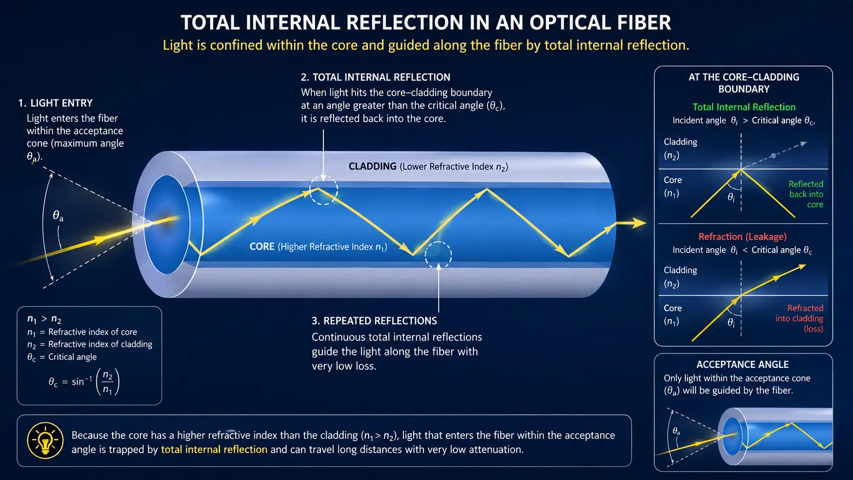
Why Is Fiber Optics Faster Than Copper Cabling?
Fiber optics is faster than copper primarily because it transmits data using light rather than electrical signals. Light can travel through optical fiber at very high speeds with extremely low signal loss, while copper signals experience greater resistance, attenuation, and electromagnetic interference. Fiber also provides vastly greater bandwidth, allowing much more data to be transmitted simultaneously over a single fiber. This makes fiber ideal for high-speed applications such as data centers, telecommunications networks, and long-distance connections. While the propagation speed of light in fiber is slightly lower than the speed of electrical signals in copper, fiber’s enormous bandwidth, low attenuation, and immunity to electromagnetic interference make it capable of supporting much higher data rates over much longer distances.What are the types of optical fiber?
Optical fiber is generally categorized into two main types: single-mode and multimode. In single-mode fiber, the core is extremely small—typically around 8 to 10 microns—and allows only one mode of light to propagate, enabling high-bandwidth transmission over long distances. There are various types of single-mode optical fibers, each designed for specific applications and performance characteristics. These include cutoff-shifted, dispersion-shifted, non-zero dispersion-shifted, bend-insensitive, and pure silica core fibers. To gain a deeper understanding of these fiber types and other key aspects of optical communication, consider joining one of our fiber optic training workshops. Multimode fiber, on the other hand, has a larger core—commonly 50 microns—which makes it easier to couple light into the fiber and allows for the use of lower-cost transmitters. Some earlier versions of multimode fiber featured even a larger core of 62.5 microns. While multimode fiber supports cost-effective electronics—despite the fiber itself being more expensive—it is well-suited for short-reach applications such as those in data centers. However, it is limited in both transmission distance and data-carrying capacity. As data rates continue to increase across the industry, many organizations are shifting toward single-mode fiber—even for short-reach scenarios—due to single mode fiber’s superior performance and scalability.Detailed Feature Comparison - Single Mode and Multimode
| Parameter | Single-Mode Fiber (SMF) | Multimode Fiber (MMF) |
| Standard Classifications | OS1, OS2 | OM1, OM2, OM3, OM4, OM5 |
| Core Diameter | 8.3 – 9 µm | 50 µm (OM2–OM5) or 62.5 µm (OM1) |
| Cladding Diameter | 125 µm | 125 µm |
| Light Propagation | Single ray/mode along core center | Multiple rays/modes bouncing off cladding |
| Light Sources | Lasers (DFB, FP, EML, Coherent) | VCSELs (850 nm) or LEDs (legacy) |
| Primary Wavelengths | 1310 nm, 1550 nm, 1625 nm (plus C/L-band DWDM) | 850 nm, 1300 nm (850–953 nm for OM5 SWDM) |
| Limiting Factor | Chromatic dispersion & attenuation | Modal dispersion (differential mode delay) |
| Typical Maximum Reach | Up to 40 km+ (unamplified); thousands of km with DWDM/amplifiers | 100 m – 550 m (depending on speed & OM rating) |
| Jacket Color Standard (TIA-598) | Yellow (OS1/OS2) | Orange (OM1/OM2), Aqua (OM3/OM4), Erika Violet (OM4 variant), Lime Green (OM5) |
| Cable vs. Optic Cost | Cheaper cable media; higher transceiver cost (laser optics) | Slightly higher cable media; lower transceiver cost (VCSEL optics) |
| Primary Applications | Telco WAN/MAN, Long-haul, FTTH, Hyperscale Campus, Data Center Interconnect (DCI) | Enterprise LANs, Intra-rack/Intra-row Data Center patches, SANs |
What are the different types of single-mode fiber
Although many people are familiar with multimode and single-mode fiber, fewer are aware that there are several different types of single-mode fiber, each optimized for specific applications. ITU-T G.652 is the most widely deployed standard single-mode fiber and is commonly used in terrestrial networks. G.653 is optimized for dispersion-shifted operation, while G.654 is designed for very low loss and is used in some long-haul terrestrial systems. G.655 provides non-zero dispersion-shifted fiber for dense wavelength-division multiplexing (DWDM), and G.656 is optimized for wideband DWDM operation. G.657 fibers are bend-insensitive fibers designed for access and other applications requiring tight bends. With modern coherent systems, G.652 fiber is used predominantly in terrestrial networks, with G.654 used in some high-capacity applications. Specialized single-mode fibers, including several designs developed for submarine cables, are also used in undersea systems.ITU-T Single-Mode Fiber (SMF) Standards Comparison
| Standard | Name / Category | Key Characteristics | Key Wavelengths | Primary Applications & Modern Context |
| G.652 | Standard Single-Mode Fiber (SSMF) | Zero dispersion at 1310 nm. G.652.D (low water peak) enables full spectrum utilization (E-band to L-band). | 1310 nm, 1550 nm | Terrestrial backbone networks, MANs, LANs. Dominates global deployment; widely paired with modern coherent optics. |
| G.653 | Dispersion-Shifted Fiber (DSF) | Shifted zero-dispersion point to 1550 nm to align with minimal attenuation window. | 1550 nm | Legacy long-haul. Obsolete for multi-channel DWDM due to severe Four-Wave Mixing (FWM) crosstalk with NRZ signals. |
| G.654 | Cut-off Shifted / Ultra-Low Loss (ULL) Fiber | Optimized for extremely low attenuation (≤ 0.15 to 0.17 dB/km) and larger effective area (Aeff). | 1550 nm, 1625 nm | Submarine networks & high-capacity long-haul terrestrial. Dominant choice for long-distance unamplified or coherent DWDM links. |
| G.655 | Non-Zero Dispersion-Shifted Fiber (NZDSF) | Introduces small, non-zero dispersion in the C-band (1530–1565 nm) to suppress Four-Wave Mixing. | 1550 nm, 1625 nm | Legacy direct-detect DWDM systems. Less critical today due to DSP-based dispersion management in coherent optical transceivers. |
| G.656 | Wideband NZDSF | Maintains controlled non-zero dispersion across a broader spectrum (S-, C-, and L-bands). | 1460–1625 nm | Wideband CWDM & DWDM networks. Designed to expand multi-wavelength capacity across extended band profiles. |
| G.657 | Bend-Insensitive Single-Mode Fiber | Engineered for low macrobending loss at tight bend radii (down to 5–7.5 mm). Subcategories: A1/A2 (G.652 compliant), B2/B3. | 1310 nm, 1550 nm, 1625 nm | FTTH/FTTx, high-density patch panels, central offices, inside-plant routing. Ideal where space constraints require sharp cable turns. |
| Submarine / Specialized SMF | Pure Silica Core Fiber (PSCF) & Large Effective Area Fiber (LEAF) | Custom silica profiles combined with large effective areas (> 100 µm²) to minimize non-linearities and signal loss over vast ocean spans. | 1550 nm, 1625 nm | Transoceanic and undersea cable systems. Essential for maximizing reach without intermediate electrical regenerators. |
What is the usable Spectrum of Optical Fiber?
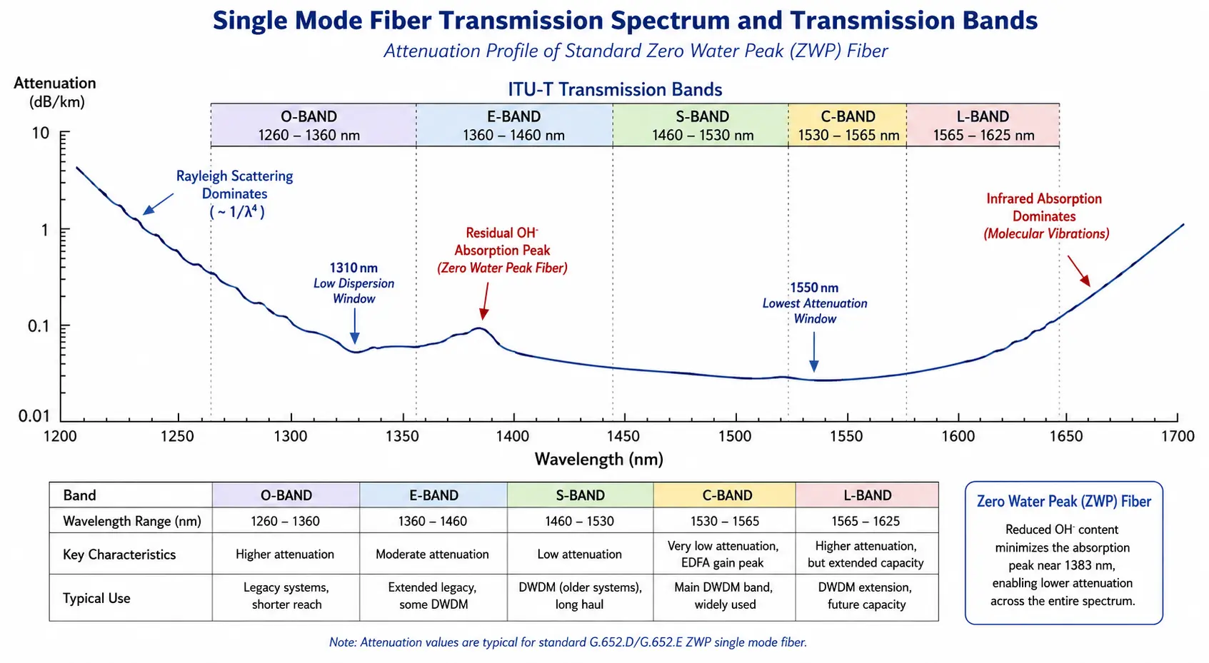 The usable spectrum of optical fiber is primarily limited by loss (attenuation), which is dominated by Rayleigh scattering at shorter wavelengths and infrared absorption at longer wavelengths. Multimode fibers typically operate at 850 nm, and sometimes 1300 nm, because these wavelengths provide practical low-cost sources and detectors with adequate attenuation for short-reach applications. Single-mode fiber initially operated near 1310 nm because standard silica fiber has a minimum in chromatic dispersion near this wavelength, enabling high-quality transmission. As fiber manufacturing improved and lower-loss transmission became possible, 1550 nm became preferred because it offers significantly lower attenuation. Optical transmission is commonly divided into the O-band (1260–1360 nm), E-band (1360–1460 nm), S-band (1460–1530 nm), C-band (1530–1565 nm), and L-band (1565–1625 nm). The C-band dominates DWDM because it combines very low fiber attenuation with excellent performance from erbium-doped fiber amplifiers (EDFAs), allowing many closely spaced wavelengths to be transmitted and amplified efficiently.
How are optical fibers manufactured?
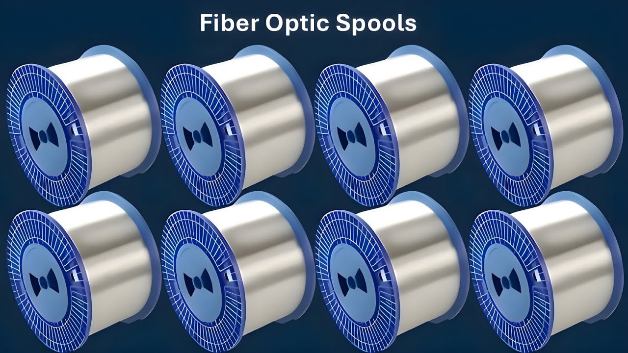
The production of fiber optic cables starts with the creation of an ultra-pure silica glass preform, which incorporates both the core and cladding materials. This preform is made using one of two main techniques: Outside Vapor Deposition (OVD) or Modified Chemical Vapor Deposition (MCVD). Once the preform is ready, it is heated in a drawing tower to extremely high temperatures—typically between 1,900°C and 2,200°C (3,450°F to 4,000°F)—and drawn into thin strands of optical fiber with a uniform diameter, usually around 125 microns. Immediately after drawing, the fiber is coated with protective polymer layers to preserve its structural integrity and ensure optimal optical performance. The coated fiber is then wound onto spools, with standard lengths ranging from 25 to 50 kilometers, depending on manufacturing requirements. During the drawing process, the fiber is also subjected to high tensile stress—typically between 100 and 200 Kpsi—to ensure its mechanical strength.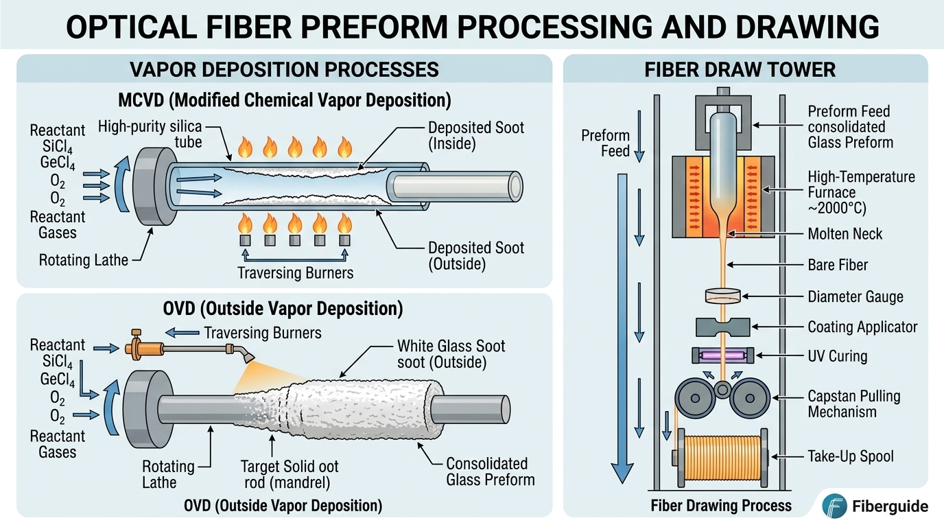
What is fiber optic cabling?
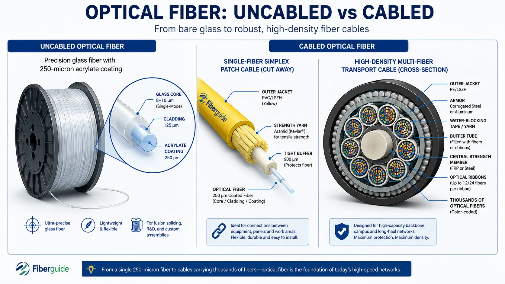
Fiber optic cabling involves protecting and organizing optical fibers into a cable structure suitable for installation and long-term use. Since bare optical fiber is extremely thin and fragile, cabling is essential to provide mechanical protection, environmental resistance, and ease of handling during deployment. Various materials are used in cabling, including strength members (such as aramid yarn or fiberglass), water-blocking gels or tapes, buffer tubes, and outer jackets made of materials like PVC, PE, or LSZH (Low Smoke Zero Halogen), depending on the environment—indoor, outdoor, aerial, underground, or submarine. Cabling configurations vary based on application. For instance:- Tight-buffered cables are used in indoor environments and short runs.
- Loose-tube cables are preferred for outdoor or long-haul installations due to their water resistance and thermal protection.
- Armored cables are used in high-risk environments where physical protection is critical.
- Simplex or duplex cables contain 1 or 2 fibers for basic connections.
- Distribution cables typically have 4 to 24 fibers.
- Trunk or backbone cables can include 48, 72, 144, or even up to 864 fibers for large-scale networks such as data centers or metro networks.
What are the applications of fiber optics?
Fiber optics is the most advanced transmission medium available, offering exceptional performance across a wide range of communication and non-communication applications. Below is an overview of some key areas where fiber optics are used.Telecommunication Applications
These are the most common and high-volume uses of fiber optics. Core networks—also known as backbone networks—are the central part of a telecommunications network that provide high-capacity, long-distance data transmission between major nodes, data centers, and other networks. They form the foundation of modern internet and communication infrastructure. Terrestrial long-haul networks are high-capacity fiber optic communication systems that transmit data over long distances across land, typically spanning hundreds to thousands of kilometers. They form the backbone of national and continental telecommunications infrastructure and are critical for carrying internet, voice, video, and enterprise data traffic between cities, regions, and countries. Submarine networks are high-capacity fiber optic cable systems installed under oceans and seas to transmit data between continents and countries. They form the global backbone of the internet, carrying more than 95% of international data traffic, including internet, voice, video, and private enterprise data. 5G transport is the underlying network infrastructure that connects different elements of the 5G ecosystem, ensuring that data flows reliably and with ultra-low latency between devices, radios, and data centers. It is a critical component that enables the performance, scalability, and flexibility that 5G promises. Fiber access network is the part of a telecommunications network that connects end users—such as homes, businesses, or cell towers—to the core network using fiber optic cables. Intra- and inter-data center connectivity is the network infrastructure used to connect devices within a single data center or connect multiple data centers together, respectively. Both are essential for enabling high-speed, low-latency communication between servers, storage systems, and applications.Non-Telecom Applications
Fiber optics are also widely used beyond traditional communication systems. Non-telecommunication applications include medical devices, industrial monitoring, security systems, lighting and decoration, as well as energy and utility sectors. Medical applications inlude:- Endoscopy or fiberoptic scopes for internal imaging
- Laser delivery for surgery and dermatology
- Biomedical sensing of blood oxygen, pressure, and temperature
- Structural health monitoring of pressure, strain or temperature, “smart skins”, in bridges, pipelines, dams and aircraft wings
- Hazardous area monitoring such as gas and chemical leak detection, temperature monitoring in explosive environments and fire detection and prevention.
- Perimeter intrusion detection using vibration-sensitive fibers
- Fiber optic CCTV signal transmission of high resolution videos for surveillance
- Decorative lighting (e.g., star ceilings, fountains)
- Illumination in MRI rooms as traditional lighting cannot be used due to strong magnetic fields that interferes with the imaging
- Artistic and architectural lighting
- Smart grid communication
- Downhole sensing in oil exploration
Sorry, the comment form is closed at this time.